Erection Instructions
If you require any further information please do not hesitate to contact us.
We strongly advise that the structure is erected by an experienced and competent person. Failure to do so could cause injury or damage to property. Kitbuildings will take no responsibility for any injuries or damages to people or property whilst erecting the building. The building must be lined, levelled and grouted before the fixing of any cladding, walls, panels etc.
The materials will require forklift unloading unless we have specified otherwise. Please ensure you have a suitable mechanical means of offloading the lorry on site.
Before you begin to erect the building, please ensure you have all of the correct parts. This can be done by checking the delivery note against what was delivered. This must be done within 7 days of delivery.
Do not leave timber purlins / eaves beams / sheeting rails outside because if they get wet then are in the sun they could warp.
Do not leave PVC guttering outside in the sun before it is fitted as this can cause damage. This will not be a problem once the guttering has been fitted.
The steelwork must be erected by experienced contractors to the drawings provided using fixings supplied.
If the building has fibre-cement roof sheets, these must be fitted in accordance with the information sheet provided and a Fragile Roof sign must be fixed to the building.
Health & Safety guidelines issued by the HSE should be followed at all times during construction. (www.hse.gov.uk/construction ) No responsibility is accepted for failure of any part of the building or foundations if the building is not constructed in accordance with the drawings provided.
Foundation Bases
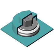
Foundations must be prepared in accordance with drawings issued and allowed to cure before the steelwork is erected. If unusual ground conditions are encountered you must consult a Structural Engineer before proceeding.
The bases must be excavated to the dimensions marked on the supplied base plan and the bolts set in the concrete accurately; diagonal check dimensions are supplied to ensure that the bolts and foundations are square and true. The foundations must then be given sufficient time to cure before erection commences.
If the building is to be erected on a concrete slab you must make sure that the depth of the slab is sufficient to carry the load of the building, the column base layout can be marked onto the slab and then drilled to take either 20mm through bolts or similar or alternatively a resin anchor system may be used.
Check all offsets shown on the layout drawing and make a note of where the TOC (top of concrete) is.
It could be flush with the finished floor level or below the finished floor level.
If it is below the finished floor level on the layout drawings it will show as T.O.C -300mm.
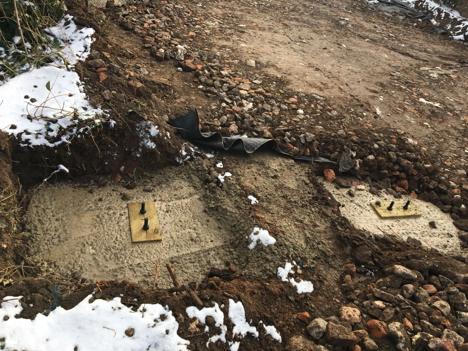
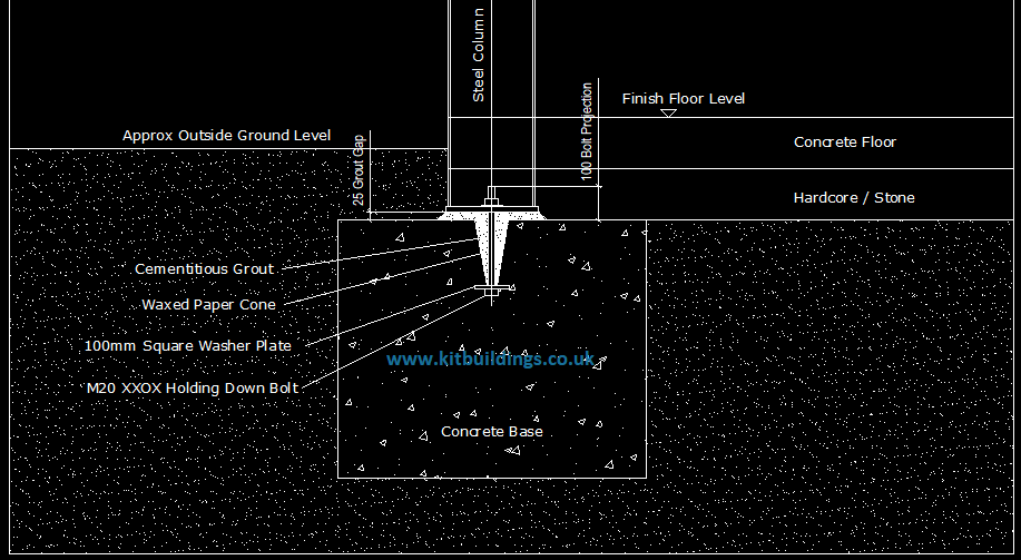
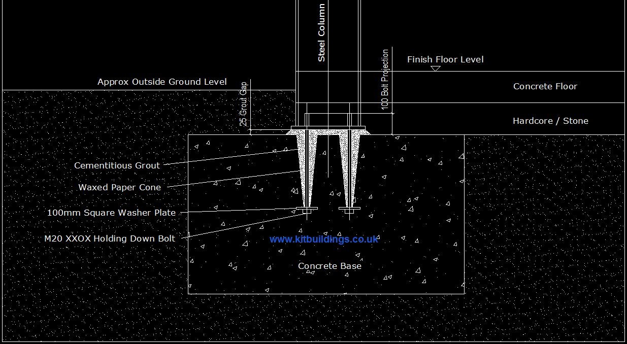
Typical foundation detail. Please ask for the correct foundation sizes for your building before commencing any ground works.
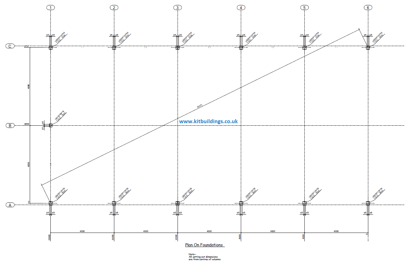
Depending on the type / size of the building there will be either 2no or 4no holding down bolts per column. This will be shown on the base plan. An example base plan is shown below. Typically we would send the base plan and holding down bolts prior to structural steelwork to allow the ground works to be done before the building arrives on site. If there are any site access restrictions please let us know as some materials may be delivered on an articulated lorry.
Before commencing, first ensure the ground is flat and level. Mark out where the building is to be located using line marking paint.
Templates
The easiest way to make sure the holding down bolts are set into the correct position is to use timber templates. These are not supplied with the kit and will have to be made on site. Cut and drill the templates to match the bolt position as shown on the base plan. Drawing a cross on the template will make it easier to line them up with the string lines. Sandwich the template between the top of the wax cone and the nut on the bolt. You may need to cut the cones down to give the correct amount of protrusion on the bolt. This is shown on the base plan. Then concrete the bolts in to the base plan using string lines. Make sure the bolt sets go in square, this can be checked using the diagonal check measurement shown on the base plan.

Once the concrte has cured, remove the templates before erecting any steelwork.
Structural Steelwork
Once the holding down bolts have been concreted in and cured, familiarise yourself with the layout drawings.
An example layout drawing is shown below.
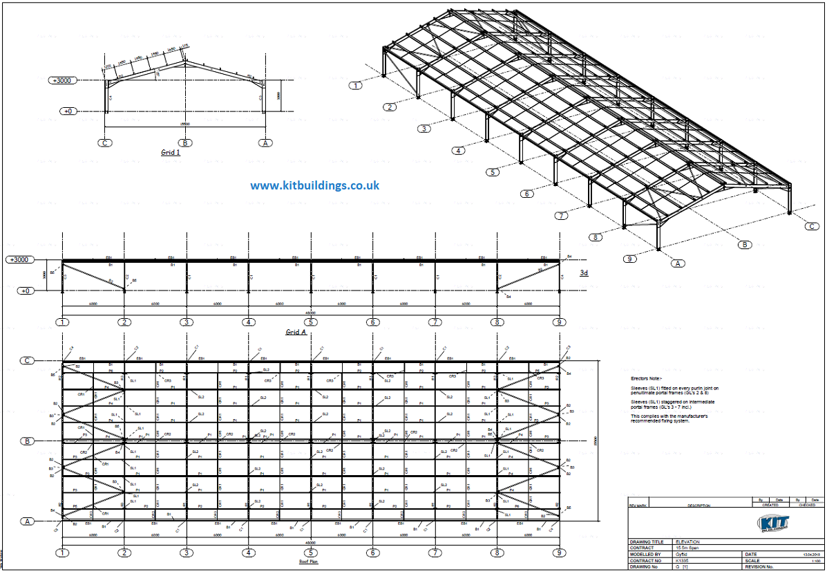
Identify all of the components and familiarise yourself with their respective positions on the 3 dimensional drawing.
All parts (Excluding the bracing) will have a number welded onto it. The number corresponds to the numbers shown on the layout and timber drawings. E.g. Columns = C1, Rafters = C1, Bracing = B1, Purlins / Eaves beams= T1
You will have been provided with a bolt site location list. This details which bolts must be used to connect each piece.
An example of this is shown below.

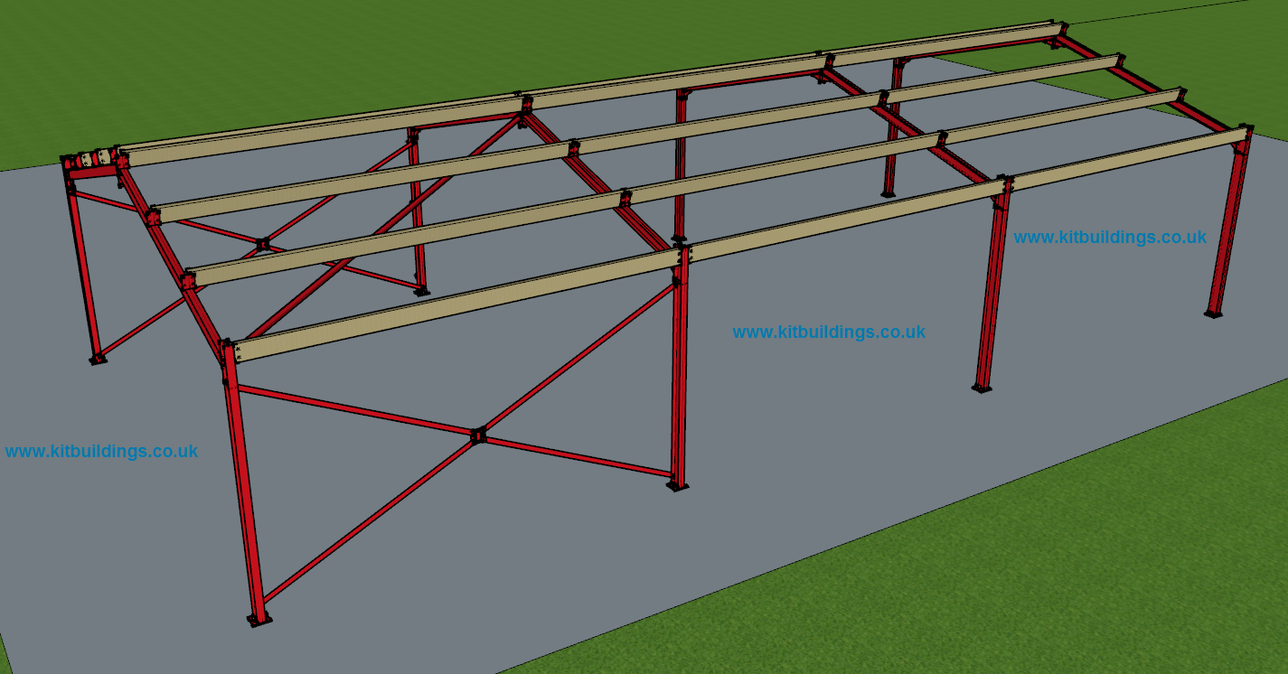
Start with the braced bay as shown below and work your way down the building.
Once the first four columns have been erected, fit the side bracing.
Then continue down the length of the building.

Assemble the first 2 rafter sets which form the braced bay – these rafters have cleats welded to the upper surface.
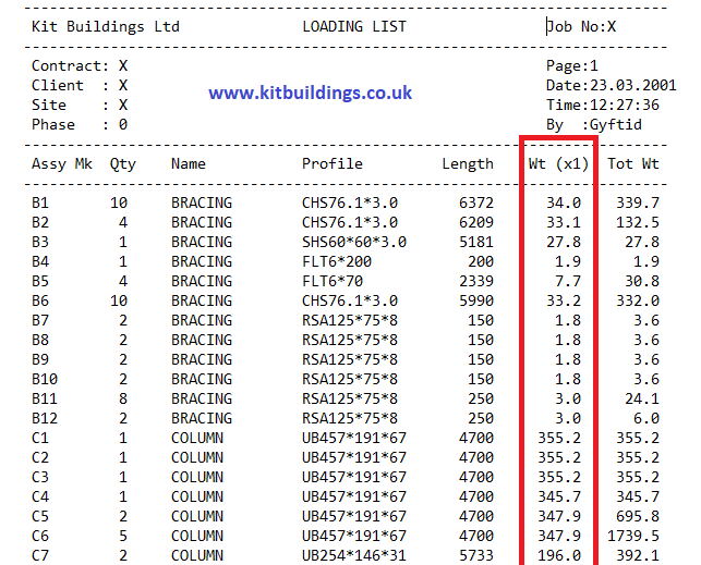
These should be bolted together on the ground and then lifted in to place. Avoid manual handling as much as possible. Use a forklift with correctly rated chains / slings. You can find out the weight of each component by looking at the loading list. The weight of each component is shown in KG. Example below.

Identify the eaves beams and purlins required.
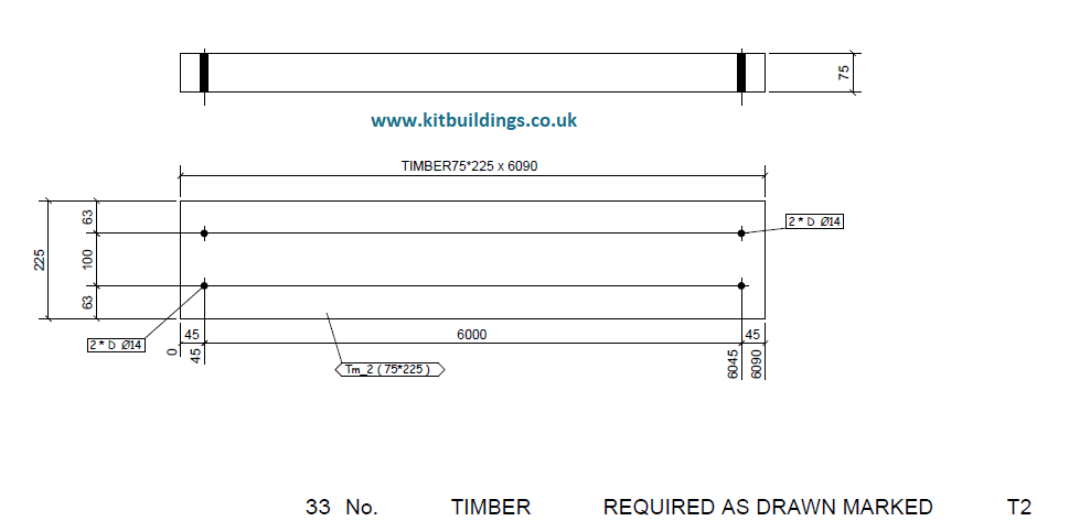
Cut and drill the timber eaves beams as shown on the timber drawings. If you are using galvanized purlins you will not have to do this as they are supplied cut and drilled. For galvanized eaves beams and purlins, the part numbers are laser etched on to them and correspond to the numbers shown on the layout drawing. Make a note of which purlins are to be sleeved, fit the sleeves and sag bars as shown in the layout drawing.
An example timber drawing is shown below.
If you are using galvanized purlins ensure they are pointing up the roof as shown in the layout drawings
Starting at the braced end of the building fit the eaves beams and the purlins. Then fit the remaining rafter sets.

Once the rafter sets have been erected, continue fitting the eaves beams first, then the purlins.
If your building has knee bracing, bolt the brace loosely to the column and when you are satisfied that the column is vertical and the eaves beam level bring up the brace until the hole in the end of the brace is in the centre of the eaves beam and then drill through the eaves beam and bolt using the coach bolts supplied; the bolt in the column can then also be tightened. Repeat this procedure on the remaining columns and eaves beams.
Below shows how typical knee bracing should be installed. The knee bracing is shown in red connecing the column to the eaves beam.

Gable Posts
Before fitting any sheeting rails to the sides of the building you will need to erect the gable posts.
These should be erected the same way as the main columns, except at the top they bolt in to a slotted cleat on the underside of the rafter.
The drawing below shows how the gable post meets the slotted cleat. The gable post and the cleat is shown in red.

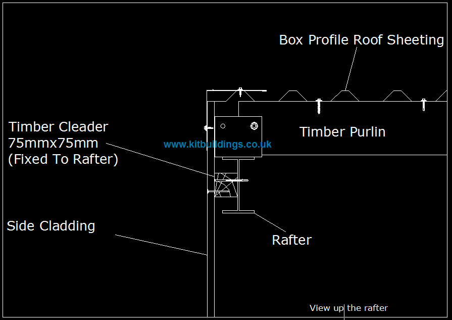
Cleader
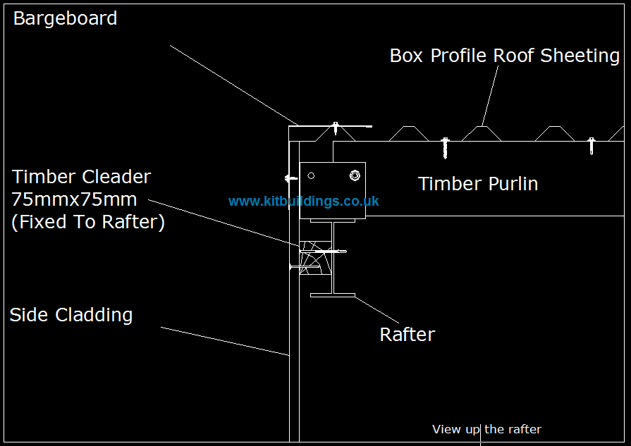
The timber rafter filler or cleader rail now needs to be fitted. The timber fits into the web of the rafter using the long Tek screws provided as shown on the gable detail drawing, the timber will be 75mm x 75mm x 3000mm.
The drawing below shows how the timber cleader should be fitted into the web of the rafter.
If the building is supplied with galvanized purlins / eaves beams / sheeting rails the cleader will also be galvanized steel.
The galvanized cleader rail should be installed as shown below

Sheeting Rails
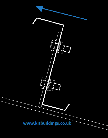
Next the 75mm x 150mm sheeting rails need to be cut to length; these can then be lifted into place, set in line with the rafter filler timber and then drilled using the cleats. The timber side rails can now be fixed using the M12 x 110mm coach bolts supplied. Alternatively the sheeting rails can be drilled on the ground to the specification shown on the timber drawings. The sheeting rails will be either timber or galvanized steel. The drawing below shows how they should be bolted into position.

When the erection sequence is complete and the building is level and true, the bolt cones need filling with non-shrink grout to stop any further movement.
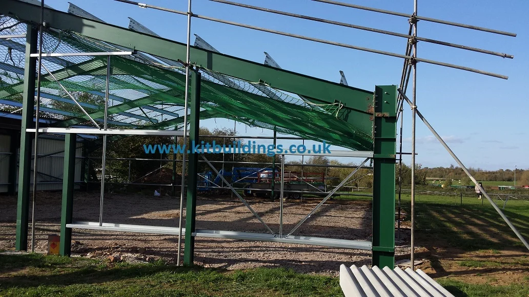
Nets & Edge Protection
Prior to installing the roof sheets it is very important to install nets and edge protection to stop you from falling off the roof.
You should also wear a fall arrest harness. However ensure you never work alone as you may need help to get back onto the roof.
A fall arrest harness is available from Screwfix for £40 incl VAT.
https://www.screwfix.com/p/delta-plus-elara130-fall-restraint-kit/6674r
If you are unable to do this, get in touch with a local scaffolder, they will usually offer this as a service.
Fixings
There are many types of fixings supplied with the cladding materials. All fixings are self drilling TEK screws and will not require drilling prior to fixing (excluding bolts). Please see the drawing below showing the different types of fixing.
Coloured caps will have also been supplied. These are used to hide the fixings when using coloured metal sheeting.
There are 19mm caps for the roof sheets and 16mm caps for the side cladding. The majority of the fixings include a washer and self sealing rubber washer.

FCT = Fixing fibre cement into timber
FCLS = Fixing fibre cement into galvanized steel (purlins / eaves beams / sheeting rails)
CSTLS = Fixing timber into galvanized steel (purlins / eaves beams / sheeting rails) (Countersunk)
CPLS = Fixing insulated composite panel into galvanized steel (purlins / eaves beams / sheeting rails)
CPT = Fixing insulated composite panel into timber
Galv Nail = Fixing Yorkshire boarding into timber
CSTHS = Fixing timber into hot rolled steel (Universal beams, columns rafters) (Countersunk)
T = Fixing metal cladding into timber (Single skin)
HS = Fixing metal cladding into hot rolled steel (Universal beams, columns rafters)
LS = Fixing metal cladding into galvanized steel
MF = Masonary fixings - Used to fix galvanized spill flashings into concrete panels.
ST = Fixing metal cladding together or roof lights into metal cladding (Often used for fixing flashings and sheet side laps)
M = Structural bolts
Coach bolt = To fix timber to hot rolled steel (Universal beams, columns rafters)
Metal Roofing
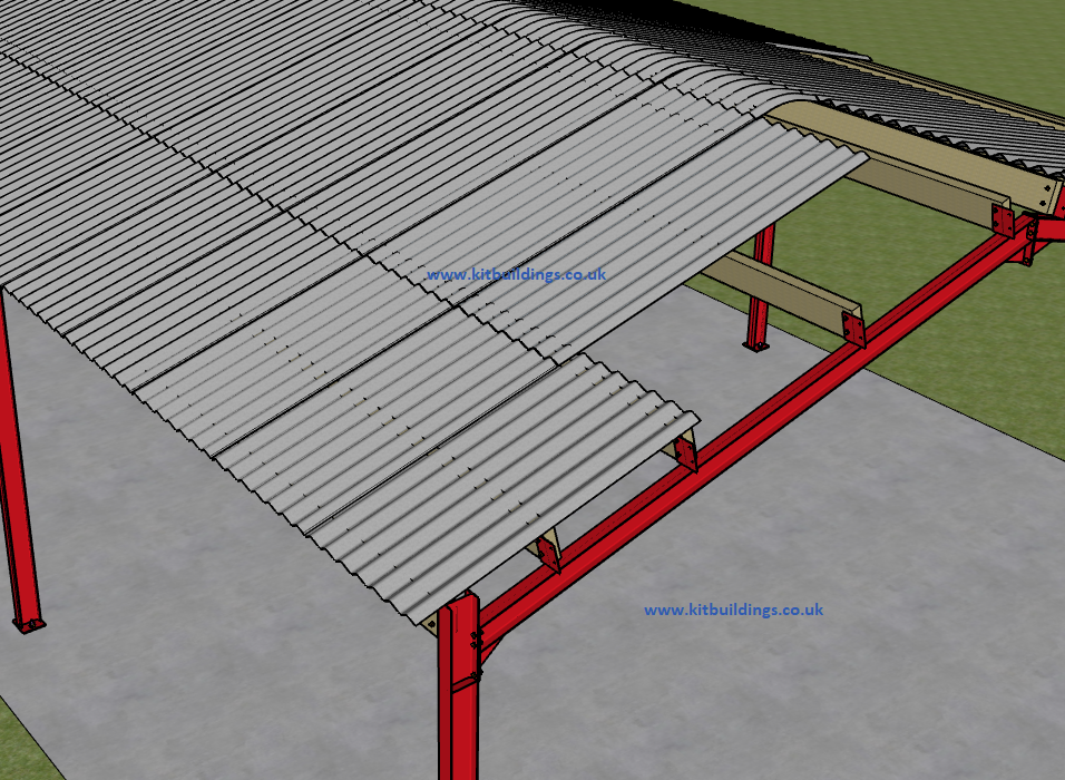
Start sheeting at the end of the building furthest away from the main prevailing wind and allow enough overhang on the sheet to reach halfway into the gutter. The sheets should extend 75mm out past the face of the side cladding, or eaves beam if there is no side cladding.
Please check the sheeting drawings. These show the correct positioning for the roof sheets.
Make sure that the first sheet is parallel with the rafter and than carry on sheeting along that elevation, check as you progress that the gutter overhang remains reasonably constant; if you are getting a saw tooth effect either the frame is slightly out of square or the first sheet is not quite parallel to the rafter. Either way it is not too great a problem as long as you check things as you go.
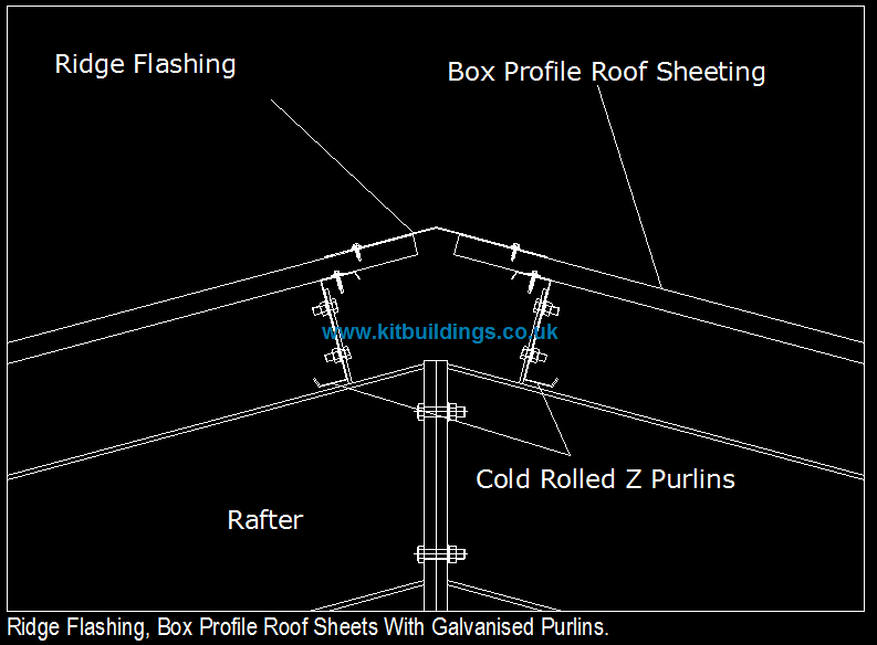
There should be 3no fixings per purlin.
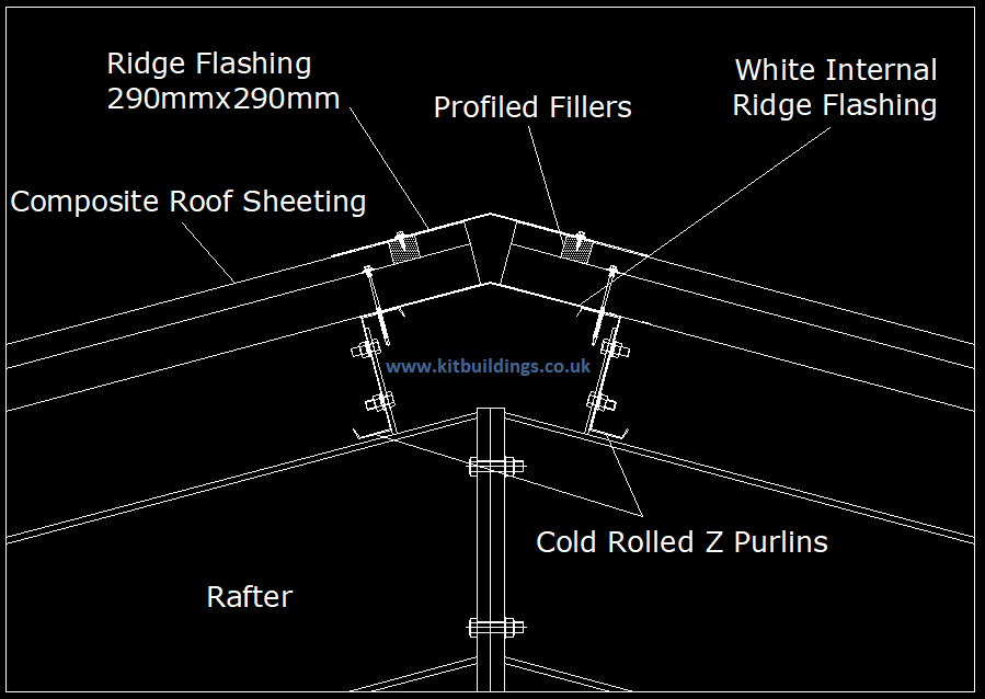
Insulated metal sheeting (Composite Panel) should be fitted in the same way. Although please note there will be an internal ridge flashing. The gap between the two ridge flashings should be filled with rockwool insulation or expanding foam.

When you reach the end of the run you may find that you have to cut a sheet longitudinally to fill the gap, if you do need a cut sheet to finish the run then you need to start sheeting the opposite elevation with the same amount of sheet cut from the offcut.

Rooflights
If your building has transparent roof lights, ensure you fix red caps to the fixings to warn others that they are fragile and not to be walked on. An example of this is shown below.
Ridge Flashing, Bargeboards & Corner flashings
The ridge flashing can now be fitted and finally the barge boards, remember to fit the barge boards starting at the eaves and move up each slope in an even manner so that the final section can be cut along the vertical face to form the ridge angle. The flashings should be fixed with stitchers. These are shown in the fixings section.
The drawing below shows how the double ridge works with an insulated composite panel roof. Foam fillers are installed between the roof sheets and the external ridge flashing.
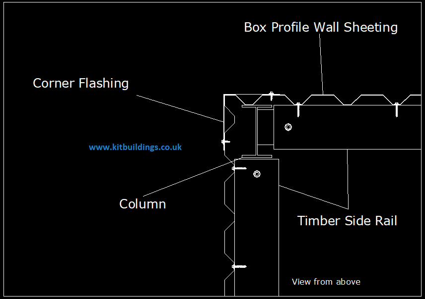
Once the side cladding has been fitted, you can fit the corner flashings. These tie the gable and the side cladding together.
Fibre Cement Roofing
We use Marley Eternit fibre cement products, they are all manufactured in the UK.
The main benefits of a fibre cement roof are the following;
Rust, rot and corrosion resistance
Excellent acoustic and thermal insulation producing a more stable environment than steel roofing products
Naturally breathable improving ventilation
Highly absorbent reducing condensation
Please check the sheeting drawings. These show the correct positioning for the roof sheets.
Fibre cement roofing products must be fitted in line with the manufacturers recommended instructions.
To see the instructions please click on the link below.
For instructions on how fit fibre cement products please click here.
Side Cladding
Please check with the sheeting drawing before cutting any sheets. If in any doubt please contact us.
If the building has only gable peak cladding, it can now be fixed as shown on the gable detail drawing. Normally the sheets are fixed in a stepped fashion and then cut to the eaves line using a shear or a nibbler (please do not use an angle grinder), depending on the building you may need to use a couple of the off cuts to finish off at the lower eaves level.
If the building has full cladding to the sides and gables, identify the sheets required and then start sheeting from the end away from the prevailing wind conditions generally experienced on the site. The gables will need to be sheeted in accordance with the supplied layout, depending on the span of the building you may need to sheet with either one long sheet straddling the gable peak or a long one each side , please check the layout drawing.
Please see a typical side cladding sheeting drawing below.

Guttering
The roof sheets should extend 75mm out from the external face of the side cladding or eaves beam.
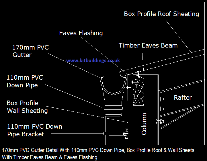
Our most popular type of guttering is 170mm deep flow PVC. If you have a different type of gutter please give us a call and we will send over fitting instructions. Do not cut any guttering without speaking to us first.
Starting from one end of the building, fit the guttering to either an eaves flashing (Metal side cladding) or directly to the eaves beam (no side cladding).
The fall of the gutter will depend on the length of the building. You will need to work out what this fall should be. There should be a gutter bracket every 660mm of gutter (6no brackets per 4m length).
The running outlets can then be fitted, then the downpipes. The quantity will depend on the size of the building.

Roller Shutter Doors
When roller shutter doors are supplied we assume that experienced fitters will be involved with the installation. If this is not the case then contact must be made with the door manufacturer for advice on fitting and pre tensioning the curtain:
Please contact us on 0845 459 4079 for the door suppliers contact information.
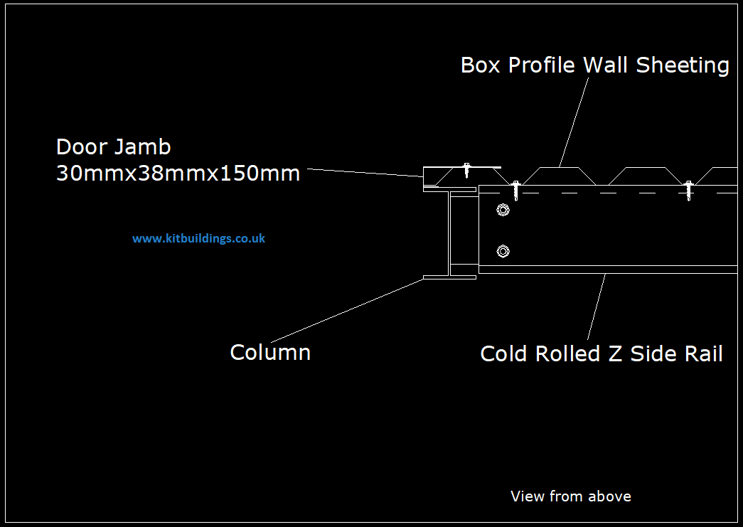
If we have supplied the roller shutter door we would have also included a drip flashing for above the door and jamb flashings to go on either side.

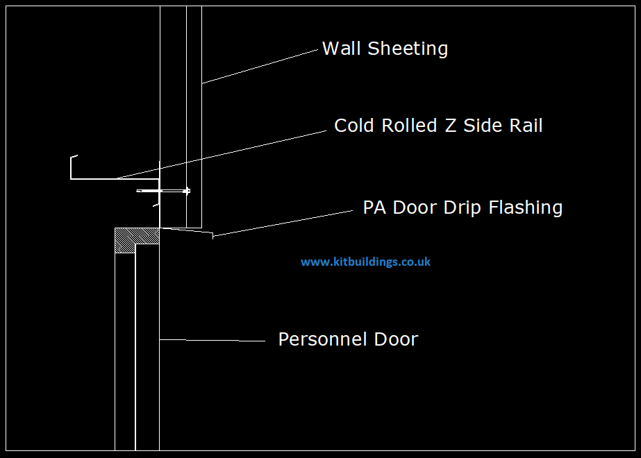
Personnel Doors
When fitting a personnel door, the frame can be aligned using the side mounted screw adjusters with an Allen key; adjustments can be made to both sides to true the frame and then fixings should be screwed through the hole in the adjusting mechanism to fix the frame.
Remove the packaging to locate the keys tied inside the head of the frame
Use the 2 loose fitters’ keys to install the door
Stand the door and frame vertically
Open the door to 90 degrees and lift off the frame
Stand the frame in the opening and insert a 12mm Allen key into each
side jacking point and wind out until each side gently touches the opening.
The door will not swing or lock correctly if the frame is not level, square and plumb in the opening
Secure the frame through the centre of each jacking point but do not over tighten as this will distort the frame
Re-hang the door onto the frame and close the door, the clearance around the head and door jambs should be parallel, if it is not the door may not lock or unlock successfully
To adjust, slacken off the specific fixing and make any adjustments using suitable shims or packing’s before re-tightening
Fit the handles and lock cover, in the door open position turn the key from both sides if all knobs throw smoothly the lock is OK
Close the door and repeat the action if the door locks and unlocks successfully it has been fitted correctly
If the locking system is stiff to lock or unlock adjust the frame as above.
Please ensure that once installed you regularly lubricate each individual locking point to help provide a smooth and problem free operation.
After installation use the Gold key to re-set the lock allowing the use of the remaining 5 keys and making the 2 fitters keys unusable.
The Gold key should not be used as an “every day” key but should be stored in a safe place and used as a “master key”.
If we have supplied the door we would have also included a drip flashing for above the door and jamb flashings to go on either side.
If you have any questions about how to erect your building please give us a call.
If you would rather somebody else does the ground work or erects the building for you, please give us a call and we will try to put you in touch with a reputable firm.
We strongly advise that the structure is erected by an experienced and competent person. Failure to do so could cause injury or damage to property. Kitbuildings will take no responsibility for any injuries or damages to people or property whilst erecting the building.